Airflow Structure Leak Prevention: 5 Design Checks
Time
Click Count
Airflow structure leak prevention sits at the intersection of product design, aerosol control, and manufacturing discipline. In regulated vaping and heat-not-burn development, a leak is rarely just a sealing defect. It can shift draw resistance, disturb aerosol delivery, increase liquid migration, and reduce yield across filling, assembly, storage, and transport.
That is why technical review increasingly looks beyond visible e-liquid escape. The more useful question is whether the airflow path remains stable under pressure changes, thermal cycling, and repeated handling. In practical terms, five design checks usually reveal most hidden risks before they become warranty, compliance, or export problems.
Why airflow leakage matters beyond the seal line
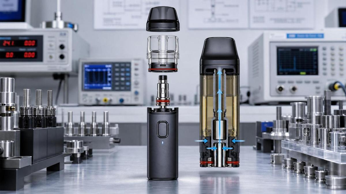
In disposable vape devices, pod systems, and HNB hardware, airflow structure leak prevention affects more than user experience. It shapes pressure balance inside the device and influences how liquid, vapor, and condensed residue move through internal channels.
A device may pass a simple leak test yet still fail in field conditions. Small bypass gaps can change inhalation resistance, upset coil feeding behavior, or pull condensate into unintended zones. The result may appear as spitback, weak aerosol output, flooding, or inconsistent puff profiles.
From an EVTS industry perspective, this matters because product consistency is now reviewed alongside regulatory readiness. Aerosol testing, traceability, and quality documentation all become harder when the airflow path behaves differently from one lot to another.
For exporters and OEM or ODM operations, leak prevention also touches shipping performance. A structure that seems acceptable at room pressure may open micro-gaps during altitude change, vibration, or temperature swings. That turns a design issue into a supply chain risk.
The first design check is the complete airflow route
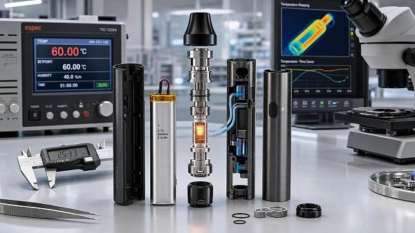
Airflow structure leak prevention starts with mapping the entire route, not only the intake hole. Air enters, travels through channels, interacts with the heating zone, and exits through the mouthpiece. Each transition point can create an unintended leakage path.
The most common mistake is treating airflow and liquid management as separate systems. In reality, they are coupled. When pressure drops in one chamber, liquid may move across porous media, weld edges, or fit gaps that looked harmless during static inspection.
A useful review asks three questions:
- Where is the intended airflow route?
- Where can bypass air enter or exit?
- How does that bypass affect liquid position and aerosol formation?
This check is especially important in compact disposable designs, where the battery cavity, reservoir shell, center tube, and mouthpiece interface are tightly stacked. A very small mismatch can create a meaningful secondary path.
What to examine closely
- Transitions between molded parts and inserts
- Air channel corners where flash or sink marks appear
- Openings near condensate collection areas
- Shared boundaries between airflow and battery compartments
The second check is sealing interface geometry
Many leakage problems come from interface design rather than seal material failure. Airflow structure leak prevention depends on how mating parts compress, align, and retain contact over time.
Flat-to-flat interfaces often look simple, but they can be unforgiving when molded parts shrink unevenly. Ribbed or stepped geometries may improve alignment, yet they can also introduce local stress points if compression is not balanced.
Ultrasonic welding adds another layer. Weld energy can distort nearby channels or sealing lips, especially when thin walls sit beside airflow passages. A part may seal well at the weld seam while opening a micro-leak beside it.
For that reason, design review should include both nominal geometry and post-assembly geometry. The important structure is the one that exists after welding, press-fit, or snap engagement, not only the CAD ideal.
Typical weak points
The third check is material behavior under real conditions
Airflow structure leak prevention is often undermined by assuming that material dimensions remain constant. In practice, plastics absorb stress, relax under load, and respond differently to nicotine formulations, flavor systems, and temperature exposure.
A seal that performs well after assembly may weaken after storage. A rigid insert may hold shape at first, then shift because adjacent soft material creeps. These changes are small, but airflow systems are sensitive to small changes.
This is especially relevant around ceramic coil modules, mesh heating assemblies, and fluidic interfaces. Material compatibility affects not only chemical resistance, but also dimensional stability around air and liquid boundaries.
A stronger evaluation method combines:
- initial leak performance
- performance after thermal cycling
- performance after filled storage
- performance after transport simulation
That sequence shows whether airflow structure leak prevention is truly robust or only acceptable at the start of the process.
The fourth check is tolerance stack-up in assembly
Many hidden leaks are assembly problems disguised as design problems. The drawing may be correct, but the cumulative tolerance across shell parts, seals, tubes, coil seats, and caps shifts the final geometry enough to open a bypass path.
This is where airflow structure leak prevention becomes a production issue. Automated lines may install parts with acceptable force, yet still leave variation in insertion depth, angular position, or weld collapse. Those differences alter channel dimensions and interface compression.
A practical review does not stop at individual tolerances. It asks how the full stack behaves in worst-case combinations. That is often where lot-to-lot inconsistency begins.
In filling and assembly operations, this check supports better process capability because leak prevention becomes measurable in relation to fixture control, tool wear, and in-line inspection.
Useful indicators during validation
- draw resistance variation across samples
- pressure decay differences by cavity location
- visual shift in tube or seal seating
- leak failures concentrated after welding or filling
The fifth check is verification under use and compliance scenarios
The final check links design intent to real validation. Airflow structure leak prevention should be verified under conditions that reflect shipping, storage, repeated puffing, and regulatory test preparation.
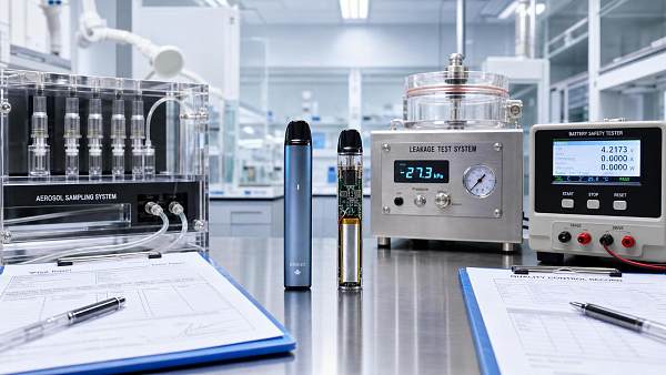
Bench testing alone may miss failures caused by orientation changes, intermittent heating, or condensate accumulation. Devices can behave differently after several puff cycles than they do in a single static pressure test.
In a regulated product environment, this matters because leakage can distort aerosol chemistry results, puff count claims, and overall product repeatability. It may also complicate investigations during PMTA preparation, TPD review, or internal quality audits.
For that reason, verification should connect design review with manufacturing evidence. A leak prevention claim is stronger when it is supported by structural review, process validation, and repeatable test data rather than one isolated pass result.
How to use these checks in day-to-day evaluation
These five checks work best as a screening framework. They help compare designs before tooling changes, supplier approval, pilot runs, or export scale-up. They also help separate cosmetic leakage concerns from deeper airflow path instability.
A concise review flow may look like this:
- map the intended and unintended airflow routes
- review interface geometry after assembly effects
- check material stability with filled and heated conditions
- model tolerance stack-up against production reality
- verify performance through use-based and compliance-relevant tests
For businesses tracking the next-generation nicotine supply chain, that approach makes airflow structure leak prevention easier to judge across component suppliers, finished devices, and manufacturing lines. It also creates a clearer basis for supplier comparison, root-cause analysis, and documentation.
The next step is usually not a full redesign. It is a tighter review of where airflow, sealing, materials, and assembly meet. Once those interactions are visible, the right test plan and the right corrective action become much easier to define.
Recommended News
 Jul 28, 2026Mesh Coil Aerosol Generation: Key Factors Behind Output StabilityProf. Elena Sterling
 Jul 28, 2026EU TPD Draft Tightens Child-Resistant Packaging TestsToxicology & Compliance Fellow
 Jul 27, 2026Vape Raw Materials Cost Breakdown: What Drives Price Swings in 2026Mr. Julian Thorne
 Jul 27, 2026FDA PMTA Update Shifts HPHCs Testing to ISO 20743:2026Toxicology & Compliance Fellow
 Jul 26, 2026Tobacco Heating Element Design: Key Factors for Stable Aerosol OutputThermal Pyrolysis Expert
 Jul 26, 2026EU TPD Draft Tightens Child-Resistant Packaging TestsToxicology & Compliance Fellow
 Jul 25, 2026Vape Testing Protocols in Canada: Key Compliance ChecksDr. Silas Vance
 Jul 25, 2026FDA PMTA Update Mandates ISO 19475:2026 for HPHCsToxicology & Compliance Fellow
 Jul 24, 2026Tobacco Product Import Regulations: Exporter Compliance ChecklistDr. Silas Vance
 Jul 24, 2026EU TPD Draft Tightens Child-Resistant Packaging TestsToxicology & Compliance Fellow
 Jul 23, 2026How to Evaluate an Ultrasonic Welding Vaping FactoryVape Production Strategist
 Jul 23, 2026FDA PMTA Guide Shifts HPHCs Testing to ISO 20754:2026Toxicology & Compliance Fellow
 Jul 22, 2026Vape Industry Testing Standards: Key Compliance Checks in 2026Dr. Silas Vance
 Jul 22, 2026EU TPD Draft Tightens Child-Resistant Packaging TestsToxicology & Compliance Fellow
 Jul 21, 2026Vape Heat Dissipation Design: What Improves Device Stability?Vaping Hardware Architect
 Jul 21, 2026FDA PMTA Update Tightens HPHCs Batch TestingToxicology & Compliance Fellow
 Jul 20, 2026Vape Thermal Stability: How Heat Affects Aerosol ConsistencyProf. Elena Sterling
 Jul 20, 2026EU TPD Draft Adds Child-Resistant Packaging ApprovalToxicology & Compliance Fellow
 Jul 19, 2026How to Evaluate a Vape Device Factory Before OEM OrdersVape Production Strategist
 Jul 19, 2026FDA Revises PMTA Guide for HPHCs TestingToxicology & Compliance Fellow
 Jul 18, 2026Tobacco Heating Sticks Japan: Market Access, Product Fit, and Key Compliance RisksThermal Pyrolysis Expert
 Jul 18, 2026EU TPD Draft Tightens Child-Resistant Packaging RulesToxicology & Compliance Fellow
 Jul 17, 2026Microporous Ceramic Coil Porosity: How It Affects Flavor, Wicking, and StabilityAerosol Fluidics Scientist
 Jul 17, 2026FDA PMTA Update Extends HPHCs Testing to New Aerosol SystemsToxicology & Compliance Fellow